
UHZ-158C Side-mounted Level Gauge - Explosion-proof and Anti-corrosion Model - Installation, Debugging, and Selection Guide
Model: UHZ-158C
Minimum order: 30
Temperature: -90~480℃
Medium: High pressure / high temperature / corrosive medium, closed container
Pressure: 0.6/1.6/2.5/6.3/32MPa
Installation method:
Measurement range: 300~15000mm
Output signal: Optional 4~20mA, RS485; compatible with LK series controller (switch signal)
Measurement accuracy: ±10mm
Material: Carbon steel / stainless steel 304/316L/PVC
<
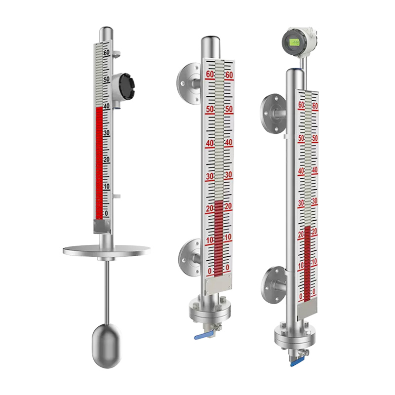
Current Image: Structural decomposition diagram of UHZ-158C side-mounted magnetic flap level gauge (magnetic float + flap indicator).jpg
Click thumbnails to switch product images
The core positioning of the UHZ-158C side-mounted liquid level gauge
The UHZ-158C series side-mounted magnetic flap liquid level gauge is an industrial-grade liquid level measurement instrument based on the principle of buoyancy and magnetic coupling technology. It is specifically designed for measuring liquid media in open or pressurized containers and can operate safely and reliably in high-temperature, high-pressure, high-viscosity, highly corrosive, and flammable and explosive conditions. It has no measurement blind spots throughout the range, with clear and intuitive display, and a wide measurement range. It is one of the core instruments in the field of industrial automation control.
This product breaks through the measurement limitations of traditional liquid level gauges and supports functional expansion through modular design. It can be equipped with a liquid level alarm switch to achieve upper and lower limit alarm control, or it can be fitted with a liquid level transmitter sensor to convert the liquid level signal into a 4-20mA standard analog signal, enabling remote detection, indication, recording, and centralized control. It is widely used in the liquid level measurement and monitoring of storage tanks, reaction tanks, fermentation tanks, boiler steam drums, and other equipment in industries such as petroleum, chemical, power, metallurgy, environmental protection, shipping, medicine, and food.
Compared with top-mounted and insertion-type liquid level gauges, the UHZ-158C side-mounted type has the advantages of small installation space requirements, convenient maintenance, and strong measurement stability. The main body tube is made of seamless steel pipe material, and the connection tube is welded by hole-pulling technology, with no internal scratches and excellent sealing performance, effectively preventing medium leakage. It is suitable for most industrial liquid media, including strong and weak corrosive media, flammable and explosive media, high-temperature and high-pressure media, and dirty media.
I. Working principle: Precise measurement mechanism driven by magnetic coupling
1. Core working principle
The core of the UHZ-158C side-mounted liquid level gauge's operation is based on the dual mechanism of "buoyancy principle + magnetic coupling transmission". The entire device consists of a measurement tube (main tube), magnetic float, flip plate indicator, flange interface, and optional remote transmission module and alarm switch. These components work together to achieve real-time detection and indication of the liquid level.
Buoyancy-driven float movement: The measurement tube is connected to the container through a flange. The magnetic float inside the tube moves up and down synchronously with the liquid level in the container. The design density of the float is precisely matched with the density of the medium, ensuring that it moves smoothly along the axis of the measurement tube under the influence of buoyancy alone, unaffected by factors such as medium flow rate and agitation, with high movement sensitivity.
Magnetic coupling-driven flip plate rotation: The float contains a high-strength magnet, and the magnetic field it generates can penetrate the measurement tube wall and form a coupling effect with the magnetic flip plates inside the external flip plate indicator. When the float rises, the magnetic field drives the flip plates to rotate. Typically, the liquid phase area is displayed in red, and the gas phase area in white. The boundary between red and white indicates the current liquid level height, providing a visual real-time indication of the liquid level. It has a wide viewing angle and clear display, allowing for easy reading at a distance and in both strong and weak light conditions.
Signal expansion (optional): If equipped with reed switches or magnetostrictive sensors, the position of the float can be detected in real time. Through electronic modules, the liquid level changes can be converted into 4-20mA standard analog signals or switch signals and transmitted to remote monitoring systems such as PLC and DCS, enabling automatic control and data traceability of the liquid level. When paired with an alarm switch, upper and lower limit thresholds can be set, and an alarm signal will be automatically triggered when the threshold is reached, ensuring production safety.
1.2 Core component function analysis
Component name Material selection Core function Optimization design points
Measurement tube (main tube) 304 stainless steel, 316L stainless steel, PP, PTFE (polytetrafluoroethylene) Accommodates the magnetic float, transmits changes in the liquid level of the medium, and isolates the medium from external components Seamless steel pipe with hole-pulling welding, no internal scratches to prevent float jamming; corrosion-resistant materials suitable for highly corrosive media
Magnetic float Stainless steel (with built-in magnet), PTFE-coated Moves up and down with the liquid level, generating a magnetic field signal Stable magnetism of the magnet, long service life; precise matching of float weight and medium density to improve measurement accuracy Flap indicator: Aluminum panel, stainless steel housing. It indicates the liquid level height by flipping the flap and is equipped with a scale ruler. The scale is laser marked and the parameters are not easy to fade. The viewing direction can be adjusted freely to suit different installation scenarios.
Flange interface: Carbon steel, 304 stainless steel, 316L stainless steel. It connects the measuring tube and the container to ensure sealing performance. It complies with national and American standards and supports customized sizes to fit different container interfaces.
Remote transmitter: Aluminum alloy housing (anti-corrosion spray coating). It converts the liquid level signal into a standard electrical signal for remote transmission. It has a two-wire design with low power consumption and is explosion-proof packaged, suitable for hazardous working conditions.
II. Core technical parameters: Detailed explanation of full working condition adaptability
The technical parameters of the UHZ-158C side-mounted liquid level gauge cover core indicators such as measurement range, accuracy, and working condition adaptability. Different configurations (standard type, high-pressure type, anti-corrosion type, explosion-proof type) have different parameters, which can be customized according to actual working conditions. The specific parameters are as follows:
2.1 General basic parameters
Measurement range: 300~18000mm, which can be customized according to the height of the container. The distance between the two flanges is the measurement range of the instrument, with no measurement blind zone.
Measurement accuracy: ±10mm, with little influence from medium density and temperature changes, and excellent measurement stability.
Medium density requirement: ≥0.55g/cm³. If the medium density is lower than 0.55g/cm³, a dedicated float can be customized to adapt.
Medium viscosity: ≤0.02Pa·S. For high-viscosity media, a non-sticking float and measuring tube can be customized to avoid medium adhesion affecting measurement accuracy.
Protection grade: IP65, dust-proof and water-proof, suitable for outdoor and humid environment installation.
Display method: Magnetic flap dual-color display (liquid phase red, gas phase white), with a scale ruler, intuitive reading, and a viewing angle range of ≥120°.
Installation method: Side-mounted, vertical installation, ensuring smooth up and down movement of the float. Installation deviation should be controlled within ±5°.
2.2 Working condition adaptability parameters
Temperature adaptability range
Standard type: -40~350℃; High-temperature customized type: -160~450℃. It can be adapted to low-temperature and easily crystallizing media through heating devices. The heating material should be non-magnetic to avoid affecting the magnetic field signal.
Pressure adaptability range
Standard type: ≤2.5MPa; High-pressure type: ≤10.0MPa; Ultra-high-pressure type: ≤32.0MPa; Special sealing structures can be customized for vacuum conditions to ensure no leakage.
Anti-corrosion performance parameters
Choose the corresponding material based on the corrosiveness of the medium. Specific adaptations are as follows: 1. Weakly corrosive media (such as tap water, engine oil): 304 stainless steel, moderate cost, wide applicability; 2. Medium-strongly corrosive media (such as acid and alkali solutions): 316L stainless steel, PTFE-coated material, excellent corrosion resistance; 3. Strongly corrosive media (such as hydrofluoric acid, chlorine gas): All PTFE material, overall sealing and anti-corrosion, preventing medium contact with metal parts.
Explosion-proof performance parameters
Explosion-proof grade: Intrinsically safe type ibⅡCT4, flameproof type dⅡBT4, suitable for Class II electrical equipment (factory use), Group C gas environment, with the highest surface temperature group T4 (135℃), and can be safely used in flammable and explosive working conditions (such as oil and chemical storage tank areas). Explosion-proof precautions: The transmitter housing must be reliably grounded, and a two-core shielded cable should be used for connection with the safety barrier. The core wire cross-sectional area should be >0.5mm², and the allowable distributed capacitance of the cable is 0.8uF.
2.3 Signal output parameters (optional)
Analog signal output: Two-wire 4~20mA DC, load resistance 250~750Ω, signal transmission distance ≤1000m, suitable for PLC and DCS systems. Switching output: Dry reed contact output, normally open/normally closed selectable, can achieve upper and lower limit alarm and control of liquid level. Contact capacity: AC220V/5A, DC24V/3A. Supports multi-contact customization.
Power supply voltage: The remote transmitter is powered by DC24V; the alarm switch does not require additional power supply and is powered by the external control system.
III. Core product advantages: Industrial scene adaptation highlights
3.1 Full-condition stable operation capability
The UHZ-158C adopts a high-sealing structure design. Through the optimization of flange sealing and welding process, it achieves a leak-proof effect and can operate stably for a long time in extreme conditions such as vacuum, high pressure, high temperature, and strong corrosion. The fault-free service life is ≥80,000 hours. The measurement tube, display part, transmitter, and alarm switch are completely isolated in terms of pressure resistance and corrosion resistance, avoiding the erosion of the medium on the electrical components and enhancing the reliability of the equipment.
3.2 Dual adaptation of visualization and automation
The on-site display does not require power supply and achieves passive indication through the magnetic coupling principle, which is energy-saving and suitable for scenarios without power supply. When paired with a remote transmission module, it can realize "on-site indication + remote monitoring" integration, meeting the needs of industrial automation control. The scale of the float indicator is marked by laser, which can withstand touch, acid and alkali gases, high and low temperatures, and other environmental influences. The parameters will never fade, and the reading clarity is not affected by the environment.
3.3 Convenient installation and maintenance, reducing operation and maintenance costs
The side-mounted design does not occupy the top space of the container, suitable for space-limited scenarios such as small and medium-sized storage tanks and reaction tanks. During installation, a valve can be added between the instrument and the container to facilitate the cutting off of materials during later cleaning and maintenance without the need to stop the machine and empty the container. The float adopts a detachable design, which is easy to replace, and is calibrated before leaving the factory. After on-site installation by the user, there is no need for complex debugging, only simple calibration is required before it can be put into use.
3.4 Modular design, flexible function expansion
The basic model only provides on-site display function. Users can flexibly select alarm switches, remote transmitters, heating devices, insulation layers, etc. according to their needs. Function upgrades can be achieved without replacing the main equipment. For example, in the pharmaceutical and food industry, sanitary flanges and PTFE materials can be selected to meet the requirements of cleanliness and corrosion resistance; in the power industry, high-temperature and high-pressure types and remote transmission modules can be selected to adapt to the liquid level monitoring of equipment such as boiler steam drums and deaerators.
IV. Installation, commissioning and calibration: Standardized operation guide
4.1 Pre-installation preparation
Unpacking inspection: Check that the instrument model, specification, and order are consistent, and check that the flange size and center distance match the container interface on site; confirm that the measurement tube, float, and float indicator are undamaged during transportation, and that the accessories (bolts, gaskets, magnetic steel calibration tools) are complete.
On-site condition confirmation: The installation location should avoid strong magnetic field interference (such as large motors, electromagnets) to avoid affecting the magnetic coupling effect; the installation area should reserve maintenance space for later maintenance; for high-temperature and low-temperature conditions, the heating and insulation devices should be arranged in advance, and the heating material should be copper, stainless steel, and other non-magnetic materials.
Pre-treatment: Remove the wire used to fix the magnetic float before leaving the factory to avoid the float from being unable to move after installation; if it is an anti-corrosion type instrument, check that the PTFE coating is undamaged and the gasket is not aged or deformed.
4.2 Installation steps
Align the instrument with the container interface through the flange, ensuring vertical installation, with a verticality deviation of ≤5° to avoid float jamming.
Insert the gasket and evenly tighten the flange bolts to ensure a tight seal and no medium leakage; for high-pressure conditions, a double gasket design should be used, and the bolt tightening torque should comply with the specifications.
If a remote transmitter and alarm switch are selected, connect the wires according to the wiring diagram, paying attention to the distinction between positive and negative poles. For explosion-proof instruments, ensure reliable grounding and single-end grounding of the cable shield to avoid interference signals. 4.3 Debugging and Calibration Process
Calibration of the Flap Indicator
Before the instrument is put into operation, use a magnet to align the flaps from top to bottom to ensure they are neatly arranged. Slowly open the liquid inlet valve to allow the medium to flow smoothly into the measuring tube. Observe whether the flaps flip smoothly and whether the red and white boundary line is consistent with the actual liquid level. If there is a deviation, loosen the clamp to adjust the position of the flaps until the indication is accurate.
Calibration of the Remote Transmitter
Connect the transmitter to the control system according to the wiring diagram, and connect the DC24V power supply. Use a multimeter to check if the power supply is normal.
Slowly adjust the liquid level in the container to the zero position of the scale, and adjust the zero position potentiometer of the transmitter to make the output current 4mA. Continue to adjust the liquid level to the full position of the scale, and adjust the full-scale potentiometer to make the output current 20mA.
Repeat the above steps 2 to 3 times to ensure that the current output is linearly corresponding to the liquid level height at any position, with an error controlled within ±1%. The instrument has been calibrated before leaving the factory. If there are no special requirements on site, no re-calibration is needed.
4.4 Installation Precautions
When the medium flows in, the valve should be opened slowly to avoid the medium impacting the float, causing the flaps to fail to flip or become disordered. If this occurs, recalibrate with a magnet.
When replacing the float, ensure that the magnetic end of the float is upward. Do not install it upside down, otherwise the measurement will fail.
No fixed impurities should enter the measuring tube to avoid the float getting stuck. Clean the main tube and the float regularly according to the medium conditions to remove deposits and impurities.
The electronic dual-color display should use the matching power adapter. If there is an abnormal display (only one segment is lit, or single-color display), check if the power supply voltage is stable. It is recommended to replace it with a DC24V 2A power supply.
5. Maintenance and Troubleshooting: Extending the Service Life of the Equipment
5.1 Key Points for Daily Maintenance
Regular Inspection (once a month)
Check if the flap indication is clear and the flipping is smooth, without jamming or discoloration; check if there is any medium leakage at the flange interface and the sealing area; check if the wiring is firmly connected without loosening, aging or corrosion. For explosion-proof instruments, the grounding resistance should be ≤ 4Ω.
Regular Cleaning (once a quarter)
Use a soft cloth to wipe off the dust and stains on the surface of the flap indicator to avoid affecting the reading. For viscous media, close the valve to empty the measuring tube, clean the inner wall of the measuring tube and the float, remove the medium adhering layer, and reinstall and recalibrate after drying.
Seasonal Maintenance
In winter, check if the heating device is operating normally to prevent medium crystallization and blockage of the measuring tube. In summer, check if the instrument housing is well ventilated and the electrical components are not overheating. Check if the anti-corrosion coating is not aging or peeling off.
5.2 Common Faults and Solutions
Fault Phenomenon Reasons for Fault Solutions
Flaps do not flip or flip with difficulty 1. The float is stuck by impurities; 2. Strong magnetic field interference; 3. The magnetic force of the float magnet has weakened; 4. The installation is not vertical 1. Clean the measuring tube and the float to remove impurities; 2. Avoid strong magnetic field sources or install anti-magnetic shielding; 3. Replace the float; 4. Adjust the installation verticality
No output or large fluctuations in the remote signal 1. Power supply failure; 2. Poor contact or short circuit in the wiring; 3. Transmitter damage; 4. Deviation between the float and the sensor position 1. Check if the DC24V power supply is normal; 2. Check the wiring, tighten the connections, and repair short circuits; 3. Replace the transmitter; 4. Calibrate the position of the float and the sensor
Leakage at the flange interface 1. Aging or damage of the sealing gasket; 2. Uneven tightening of the bolts; 3. Damage to the flange surface 1. Replace the sealing gasket; 2. Tighten the bolts evenly, following a diagonal sequence; 3. Repair or replace the flange Large deviation between the flip plate indication and the actual liquid level
1. The flip plate position is not calibrated.
2. The float density does not match the medium density.
3. There are air bubbles in the measuring tube.
1. Re-calibrate the flip plate position with a magnetic steel.
2. Replace the float with one suitable for the medium density.
3. Remove the air bubbles in the measuring tube.
Abnormal alarm of explosion-proof instrument
1. Poor grounding.
2. Safety barrier failure.
3. The cable shield is not grounded at one end.
1. Check the grounding circuit to ensure reliable grounding.
2. Replace the safety barrier.
3. Adjust the grounding method of the cable shield.
VI. Industry application scenarios: Precisely adapting to demands across multiple domains
6.1 Petrochemical industry
Suitable for crude oil storage tanks, refined oil storage tanks, chemical reaction tanks, acid and alkali storage tanks, and other equipment, it measures media such as crude oil, gasoline, diesel, acid and alkali solutions, and chemical intermediates. Made of 316L stainless steel or PTFE corrosion-resistant material, paired with an explosion-proof remote transmission module, it enables real-time monitoring and remote alarming of liquid levels in flammable, explosive, and highly corrosive conditions, ensuring production safety and preventing medium leakage and waste.
6.2 Electric power industry
Applied to equipment such as boiler drums, high and low-pressure heaters, deaerators, drain tanks, and return water tanks, it measures media such as water and heat transfer oil. High-temperature and high-pressure instruments are selected, capable of withstanding temperatures above 350°C and pressures above 10 MPa. Equipped with a 4-20 mA remote transmission module, it is connected to the power plant DCS system to achieve automatic level regulation, ensuring stable boiler operation and avoiding dry burning accidents.
6.3 Pharmaceutical and food industry
Suitable for fermentation tanks, batching tanks, clean storage tanks, and other equipment, it measures media such as chemical solutions, food ingredients, and purified water. Made with sanitary flanges and PTFE materials, it eliminates sanitary dead zones, meets food and pharmaceutical cleanliness standards, and prevents media contamination. The basic passive display design is suitable for cleanrooms without additional power supply, ensuring production compliance.
6.4 Environmental protection and water treatment industry
Applied to equipment such as sewage storage tanks, clean water reservoirs, and chemical storage tanks, it measures media such as sewage, chemical solutions, and clean water. The selected anti-corrosion instrument is resistant to corrosion from sewage and chemicals, with a protection level of IP65 suitable for outdoor humid environments. It can achieve liquid level upper and lower limit alarms, avoiding issues such as sewage overflow and insufficient chemicals, and improving water treatment efficiency.
6.5 Shipping and metallurgical industry
Shipping industry: compatible with fuel tanks, lubricating oil tanks, ballast water tanks, and other equipment, capable of withstanding ship's roughness and vibration conditions, with stable measurement and no jamming; metallurgical industry: compatible with metallurgical furnace cooling water tanks, lubricating oil storage tanks, and other equipment, capable of withstanding high temperature and vibration environments, and capable of real-time monitoring of cooling water level to ensure the normal operation of the furnace.
VII. Selection Guide: Customize an Adaptation Plan According to Your Needs
7.1 Core basis for model selection
Medium characteristics: Select the material based on the corrosivity of the medium (304 stainless steel for ordinary medium, 316L/PTFE for strong corrosion); customize the float according to the medium density and viscosity; high-temperature medium requires high-temperature instruments, and low-temperature easily crystallizing medium needs to be equipped with a heat tracing device.
Operating condition parameters: Select standard/high-pressure/ultra-high pressure models based on the working pressure of the container; choose side-mounted models (for space-constrained scenarios) based on the installation space; confirm the protection level for outdoor installation, and select explosion-proof models for flammable and explosive operating conditions.
Functional requirements: For on-site observation only, select the basic model; for remote monitoring, choose the model with a 4-20mA remote transmission module; for safety alerts, select the model with an alarm switch; for automated control needs, choose the combination configuration of "remote transmission + alarm".
Interface standard: Customize flanges according to the container interface size and flange standard (GB, US system) to ensure installation compatibility.
7.2 Typical selection cases
Case 1: Petrochemical crude oil storage tank
Operating conditions: medium crude oil (density 0.85g/cm³, viscosity 0.015Pa·S), working pressure 1.6MPa, working temperature 80℃, flammable and explosive environment, requiring remote monitoring and alarming. Selection scheme: UHZ-158C side-mounted type (304 stainless steel material) + explosion-proof remote transmitter (4-20mA) + liquid level alarm switch, flange size DN50 (GB), measurement range 2000mm.
Case 2: Power plant boiler drum
Operating conditions: medium water (saturated steam condition), working pressure 10MPa, working temperature 300℃, requiring integration into the DCS system for automated control. Selection plan: UHZ-158C high-pressure high-temperature type (316L stainless steel material) + high-temperature remote transmitter, flange size DN80, measurement range 3000mm, equipped with a heat tracing device to prevent crystallization.
Case 3: Acid-base dosing tank in the pharmaceutical industry
Operating conditions: medium sulfuric acid solution (concentration 30%), working pressure 0.6MPa, working temperature 25℃, clean environment, no additional power supply. Selection scheme: UHZ-158C corrosion-resistant type (fully PTFE material), sanitary flange, basic passive display, measurement range 1500mm.
8. Summary
The UHZ-158C side-mounted magnetic flap level gauge has become the preferred instrument in the field of industrial level measurement due to its full-condition adaptability, modular functional design, and convenient installation and maintenance characteristics. It can accurately meet the level monitoring needs of various industries such as petrochemical, power, pharmaceutical, and environmental protection. This article provides a detailed explanation from core dimensions such as product technical parameters, working principles, installation and debugging, application selection, and fault handling.
Send Inquiry